What is 3D CAD Modeling?
Let’s start with the question, what is CAD? The acronym CAD stands for Computer Aided Design and covers a wide variety of design tools used by several industry professionals like architects, game designers, artists, manufacturers, and of course engineers. CAD systems help their users by performing thousands of complex geometrical calculations in the background without anyone having to even think about it. This makes the designer’s job a whole lot easier and frankly more fun, because everybody loves doing pages of math by hand, right?
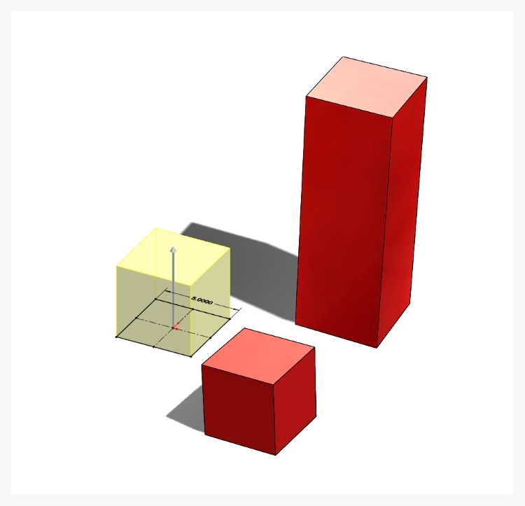
By extruding a 2D sketch, a solid cube is created. By extruding the 2D sketch farther, a rectangular block is created.
So where does the 3D (3-dimensional) part of 3D CAD Modeling come in? CAD started with being limited to just 2D capabilities (like drawing on a flat sheet of paper). You could design/draw objects using basic views; top, bottom, left, right, front, back, and an angled view called isometric. It basically worked just like drawing something in 2D on paper, but the complex math was done for you. Then came along 3D CAD programs which allowed the user to take these 2D views and “pull” them out of the page into a 3D object on the screen. Think of drawing a 2D square on a piece of paper and then pulling it out of the page into a cube, or pulling it really far into a long rectangular bar. This is what 3D CAD Modeling allows us to do, all in the computer program.

Example of highly complex shapes that are possible with modern 3D CAD Modleing software. Here we're using SolidWorks.
But we’re not limited to just rectangles. We can create basically unlimited complex shapes of all sizes and forms… the only real limitation is the user’s imagination. Nearly every modern day product you interact with on a day to day basis was created using 3D CAD Modeling. From every detail of your car inside and out, your TV remote, kitchen appliances, computer mouse, and even your children’s toys, all were first created in a virtual 3D CAD program.

Screen shot of the Material Options for a Finite Element Analysis.
Now what about the “modeling” part of 3D CAD Modeling? When using 3D CAD Modeling, you’re essentially creating a virtual reality object that can have all of the same properties as an actual physical object: material, weight, size, optical properties, physical properties, etc. This allows us to create a virtual “model” of how the object will behave in the real world, even before it is ever built. This is where things get really interesting and the math problems get insanely long. With 3D CAD modeling we can create assemblies of parts to see how they fit together, test how they will react to forces applied to them, drop objects to see if they will break, test the motion and interaction of moving parts within an assembly, test how fluids will flow through them, evaluate how they will be manufactured using simulations, and render near perfect images to see how products will look in real life. As you can see, once we have created a 3D CAD Model of an object, there is a lot that we can figure out from there but of course there are limitations and it is still a just model but pretty cool and extremely useful none-the-less.
Here’s a quick little example of how to create a 3D CAD Model for a corner bracket, performing a stress analysis on it, and then creating a finished photo-realistic rendering.

CAD programs convert a 2 dimensional sketch into a 3 dimensional object with a depth dimension.

A solid 3 dimensional object starts as the basis for more complex geometry to be added.

Another 2 dimensional sketch is created to add a pattern of screw holes to the part.

Once the cut command is selected, the 2 dimensional sketch of holes creates actual holes in the part.

Angled features called chamfers (pronounced like champ without the letter "p") are added to match the angles of the screw head that will go into the bracket's holes.

A copy of the holes is added to the opposite face of the bracket in one step with a mirroring command.

A design feature called gussets are added to help strengthen the bracket to resist bending forces.

Final rounding features called fillets (pronounced fill-ets like your filling a glass up, not the steak).

A photo-realistic rendering of the finished corner bracket CAD model.

A Finite Element Analysis of the structural integrity of the corner bracket. Red areas show high stress on the part and blue areas show little to no stress.
As we’re sure you’ve found, there isn’t a lot of quality information out there for inventors. If you liked this article and found it informative, please share it with your like-minded, creative, inventive friends, coworkers and family. If you need any product development assistance, feel free to Contacts Us by emailing us at info@designlaunchers.com, filling out the simplified contact form below, or giving us a call at 407-721-4390. We’re always happy to help inventors through all the stages of product development!


CONTACT US TO LEARN MORE ABOUT OUR PRODUCT DESIGN & DEVELOPMENT SERVICES:
Call us at 407-721-4390, or
Use the Contact Form and we’ll gladly help.